MEASURE OF HOW MUCH DEFORMATION BEFORE BREAK (TENSILE TEST)
USED TO MAKE STEEL SOFT & DUCTILE BY HEATING A METAL TO TEMPERATURE ABOVE CRITICAL TEMPERATURE FOR A PERIOD FOLLOWED BY COOLING @ SUITABLE RATE ACCORDING TO THE PURPOSE
A RIGID RESTRAINT PROVIDING SUBSTANTIALLY FULL FIXATION, IDEALLY NOT ALLOWING TRANSLATIONAL OR ROTATIONAL DISPLACEMENT OF THE PIPE ALONG ANY OF THE THREE REFERENCE AXES. IT IS EMPLOYED FOR PURPOSES OF RESTRAINT BUT USUALLY SERVES EQUALLY WELL AS A RESTRAINT, SUPPORT, OR BRACE.
STEEL WITH DISTINCTIVE PROPERTIES MINIMUM COMPONENT (SILICON 0.6, COPPER 0.6, MANGANESE 1.65)
Based on ASME (American Society of Mechanical Engineers) standards which involves outlining the necessary steps to ensure that welding is performed safely and effectively while maintaining high quality and integrity. Below is a comprehensive general welding procedure that can be adapted for various applications.
General Welding Procedure Based on ASME
1. Purpose and Scope
- Purpose: Define the goals of the welding process, including structural integrity, safety, and performance requirements.
- Scope: Specify the materials, types of joints, and applications covered by the procedure, such as carbon steel, stainless steel, and alloy steel welding.
2. References
- ASME Section IX: Welding and Brazing Qualifications
- American Welding Society (AWS) specifications and standards
- Material specifications (ASME B31.3, ASME B31.1, etc.)
- Manufacturer’s data sheets for filler materials
3. Welding Processes
Specify the welding processes to be used, such as:
- SMAW: Shielded Metal Arc Welding (Stick Welding)
- GMAW: Gas Metal Arc Welding (MIG Welding)
- FCAW: Flux-Cored Arc Welding
- TIG: Gas Tungsten Arc Welding
- SAW: Submerged Arc Welding
4. Welding Materials
- Base Metals: Identify the materials to be welded, including their specifications (e.g., ASTM).
- Filler Materials: Specify the type and classification of filler metals per AWS/ASME standards.
- Shielding Gases: Identify the type of shielding gas used for processes like GMAW or TIG welding (e.g., Argon, CO2, Helium).
5. Welding Joint Design
- Outline the joint configurations, including:
- Butt Joints
- Fillet Joints
- Edge Joints
- Define the joint design based on the required strength and service conditions, ensuring it is compliant with relevant ASME codes.
6. Preparation of Base Metals
- Cleaning: Remove contaminants such as rust, oil, dust, and other impurities from the surfaces to be welded.
- Fit-Up: Ensure proper fit-up of the joint with tolerances as specified in the applicable standards.
- Preheating: If necessary, preheat the base materials to reduce the risk of cracking based on material type and thickness.
7. Welding Parameters
Specify the following parameters:
- Voltage (V): Set appropriate arc voltage for the welding process.
- Current (I): Set the welding current according to the process and joint thickness.
- Travel Speed: Determine the appropriate welding speed to ensure proper bead appearance and penetration.
- Heat Input: Calculate or control the heat input to minimize distortion and prevent material degradation.
8. Welding Technique
Provide details on the technique to be used, including:
- Electrode Angle: Specify the angle of the electrode or torch relative to the workpiece.
- Weaving: Include details on weaving patterns for different joint configurations (if applicable).
- Pass Sequence: Define the sequence of weld passes (e.g., root pass, fill passes, final cap pass).
9. Inspection and Testing
- Visual Inspection: Conduct a visual examination of the welds to check for defects such as undercuts, porosity, and cracks.
- Non-Destructive Testing (NDT): Specify NDT methods (e.g., RT, UT, MT, PT) to be implemented based on service requirements to ensure weld integrity.
- Destructive Testing: Outline any requirements for tensile, impact, or bend tests if necessary according to applicable codes.
10. Post-Weld Heat Treatment (PWHT)
If required by the material or design specifications, specify post-weld heat treatment details, including:
- Temperature and duration
- Cooling rate and method
11. Safety Considerations
- Implement safety measures throughout the welding process, including:
- Personal Protective Equipment (PPE) such as helmets, gloves, and protective clothing.
- Ventilation to avoid exposure to harmful fumes.
- Equipment safety checks before operation.
12. Documentation and Records
- Maintain records of:
- Welder qualifications (per ASME Section IX)
- Welding procedure specifications (WPS)
- Inspection and testing results
- Material and filler metal certifications
13. Training and Qualification
- Ensure that personnel performing the welding are trained and qualified in the applicable welding processes, techniques, and safety practices.
Conclusion
This general welding procedure based on ASME provides a structured approach to welding operations, covering all necessary steps from planning and material selection to final inspections and documentation. Adhering to these guidelines facilitates quality assurance and compliance with industry standards, ensuring that welded structures meet performance and safety requirements. Always refer to current codes and standards for specific applications.
Based on ASME (American Society of Mechanical Engineers) guidelines involves a systematic approach to ensure that the painting process meets safety, performance, and quality standards. Below is a detailed procedure for painting piping systems, including surface preparation, material selection, application, and inspection.
Piping Painting Procedure Based on ASME
1. Purpose and Scope
- Purpose: Define the rationale for painting the piping, such as corrosion protection, aesthetics, and identification.
- Scope: Specify the types of piping systems covered by this procedure (e.g., process piping, HVAC, utility lines).
2. References
- ASME B31.3 Code for Process Piping
- NACE International Standards
- Manufacturer’s recommendations for coating materials
- Safety Data Sheets (SDS) for all chemicals used
3. Materials and Equipment
- Coatings: Select appropriate coatings based on service conditions, including:
- Primers (anti-corrosive)
- Intermediate and Topcoats (epoxy, polyurethane)
- Application Equipment:
- Brushes, rollers, or spray guns
- Airless spray equipment if applicable
- Surface Preparation Tools:
- Abrasive blast equipment
- Power tools (grinders, sanders)
- Cleaning solvents and rags
4. Surface Preparation
- Cleaning:
- Remove dirt, oil, grease, and contaminants from the surface using solvents (e.g., mineral spirits) and cleaning rags.
- Abrasive Blasting:
- Use abrasive blasting (sand or shot) to achieve a surface cleanliness level of NACE No. 2 (near-white metal) or higher, according to applicable standards.
- Power Tool Cleaning:
- For areas that cannot be blasted, power tool cleaning may be done following NACE requirements to remove loose rust and old paint.
- Inspection:
- Inspect the prepared surface for any contaminants or areas missed during cleaning.
5. Application of Coating
- Environmental Conditions:
- Ensure ambient temperature and humidity conditions meet coating manufacturer recommendations (typical range: 40°F to 90°F and relative humidity < 85%).
- Priming:
- Apply a suitable primer as per the manufacturer’s specifications.
- Ensure the primer is compatible with the topcoat.
- Topcoat Application:
- Apply the topcoat using the selected application method (brush, roller, spray).
- Follow the manufacturer’s recommendations for wet film thickness.
- For critical areas, a second coat may be warranted based on the design requirements.
6. Curing and Drying
- Ensure proper curing conditions as per manufacturer recommendations (e.g., drying time between coats, full curing timelines).
- Monitor ambient conditions during curing to prevent issues related to humidity or temperature fluctuations.
7. Inspection and Testing
- Visual Inspection: After application, visually inspect for:
- Uniform coverage
- Absence of runs, sags, or defects
- Adhesion and surface integrity
- Dry Film Thickness Measurement: Use a dry film thickness gauge to measure the thickness of applied coatings and ensure compliance with specified requirements.
- Adhesion Testing: Conduct adhesion tests (e.g., cross-hatch adhesion test) if required by the specifications to ensure coating bonds properly.
8. Safety and Environmental Considerations
- Develop and implement safety procedures including:
- Personal Protective Equipment (PPE): gloves, goggles, respirators.
- Ventilation: Ensure proper ventilation during spray application.
- Waste Disposal: Follow local regulations for disposal of paint waste and cleaning solvents.
9. Documentation
- Maintain records of:
- Material Safety Data Sheets (MSDS) for all coatings used.
- Surface preparation and painting dates.
- Inspection reports and thickness measurements.
- Conduct a final review of the inspection and testing results before full operational use.
10. Training and Qualifications
- Ensure personnel conducting the painting are trained and qualified in:
- Surface preparation techniques
- Coating application processes
- Safety procedures related to painting
Conclusion
This procedure serves as a guideline for painting piping systems, ensuring compliance with ASME and best practices for surface protection and aesthetics. Adhering to these practices will enhance the longevity of piping systems while promoting safety and operational efficiency in industrial settings.
Calculating the wall thickness of a pipe is essential for ensuring the structural integrity and safety of piping systems, especially under internal pressure. The following steps outline how to calculate the pipe wall thickness based on ASME standards, particularly ASME B31.3 for process piping.
Steps for Pipe Wall Thickness Calculations Based on ASME
1. Determine Design Parameters
- Internal Design Pressure (P): The maximum internal pressure the pipe will experience (measured in psi or Pa).
- External Pressure (Pe): If applicable, the external pressure impacting the pipe (measured in psi or Pa).
- Design Temperature (T): The maximum temperature the pipe will operate at (°C or °F).
- Pipe Diameter (D): The nominal outside diameter of the pipe (in inches or mm).
2. Identify Material Properties
- Allowable Stress (S): Obtain the allowable stress of the material at the design temperature, which can be found in ASME Section II, Material Specifications, or the material’s datasheet (measured in psi or Pa).
- Thickness Corrosion Allowance: Account for any additional thickness required for corrosion or erosion, usually expressed as a fixed value (in inches or mm).
3. Select the appropriate ASME formula
For an internally pressurized pipe, the minimum required thickness can be calculated using the following formula from ASME B31.3:
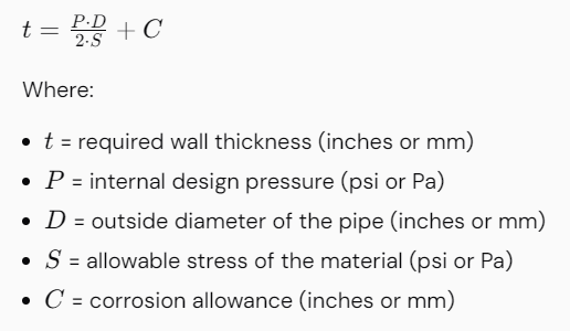
Note: For specified thickness definitions within ASME, you may also include a term for the minimum wall thickness. This can be specifically stated in different ASME sections.
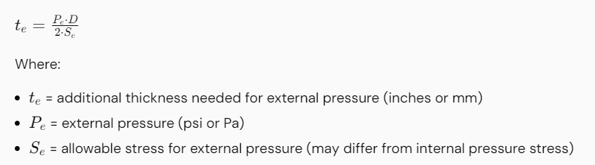
4. Account for External Pressure (if applicable)
If the pipe is subject to external pressure, you must also consider the external pressure when calculating the wall thickness. Use the formula:
5. Determine the Design Thickness
Combine thicknesses computed for internal and external pressures:
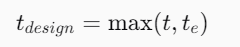
This equation helps in determining the final design thickness, accounting for both internal and external pressures.
6. Check Against Standard Pipe Schedules
Check if the calculated wall thickness meets or exceeds available standard pipe sizes and schedules (such as Schedule 40, 80). Pipe thicknesses defined by ASME pipe schedule can be found in ASME B36.10 and ASME B36.19.
7. Consider Additional Design Factors
Include any additional factors such as:
- Fatigue considerations for cyclic loading.
- Impact considerations for low-temperature applications.
Adjust the thickness accordingly if required by safety factors or specific application standards.
8. Final Review and Compliance Verification
Ensure the final design meets all relevant codes and standards (such as ASME B31.3, B31.1, etc.) and industry best practices. Perform peer reviews or checks per organizational procedures.
Summary
Calculating pipe wall thickness using ASME standards requires a comprehensive understanding of the operational conditions, material properties, and appropriate mathematical formulas. Consider the internal and external pressures, allowable stress, and corrosion allowances to ensure safety and compliance. This process is critical for the design, material selection, fabrication, and maintenance planning of piping systems. Always refer to the latest ASME codes and standards for the most accurate and safe design practices.
Calculating pressure drop in piping systems is a crucial aspect of engineering design. It helps in understanding the hydraulic performance of a pipeline and ensuring the system operates efficiently. The following steps outline the method to calculate pressure drop in a piping system based on ASME standards.
Steps for Piping Pressure Drop Calculations
1. Define Parameters of the System

2. Determine Flow Rate

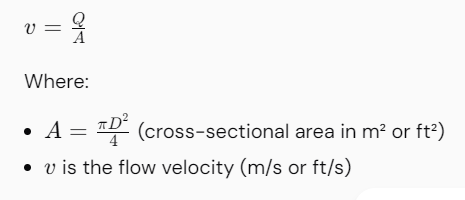
3. Calculate Flow Velocity
Using the flow rate, calculate the fluid velocity in the pipe:
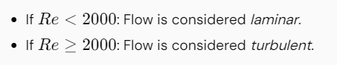
4. Calculate Reynolds Number
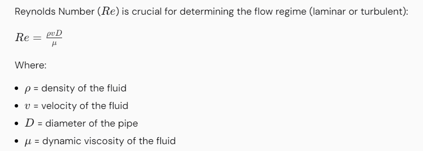
Note:
5. Determine the Friction Factor
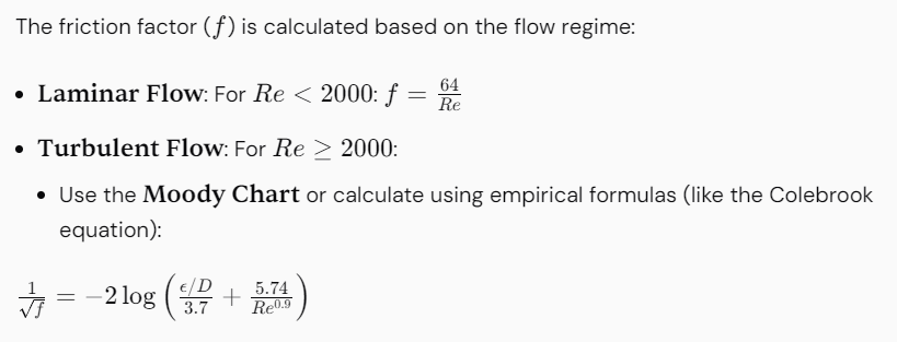
Where:

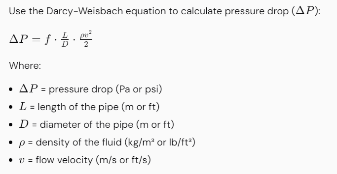
6. Calculate Pressure Drop in the Pipe
7. Include Additional Losses (if applicable)
Consider fittings, bends, valves, and other components in the piping system that contribute to pressure drop:
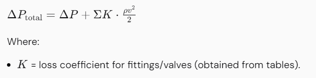
8. Calculate Total Pressure Drop
Add up the pressure drop from the straight pipe and all additional components to find the total pressure drop across the entire system.
Summary
The calculation of pressure drop in piping based on ASME standards involves understanding fluid properties, determining the flow regime, calculating friction factors, and applying the Darcy-Weisbach equation. Additional losses due to fittings and other components should also be considered. Always refer to relevant reference materials and standards for specific guidelines. This method will provide the necessary calculations to ensure efficient system design and operability.
Martensitic transformation, more commonly known as quenching and tempering, is a hardening mechanism specific for steel. The steel must be heated to a temperature where the iron phase changes from ferrite into austenite, i.e. changes crystal structure from BCC (body-centered cubic) to FCC (face-centered cubic) then “quenched” (rapidly cooled), often in oil or water
is a tee or any fitting with a branch used in pipelines that is pigged and has a restriction bar welded internally preventing the pig from traveling down a branch connection
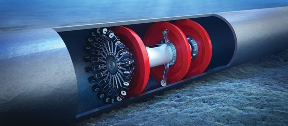
Pipeline pigging services are essential for maintaining the integrity and efficiency of various pipeline systems . The primary types of pipeline pigging include cleaning, inspection, utility, and specialized pigs, each serving a crucial role in pipeline maintenance . The global pipeline pigging market is projected to reach $6 billion by 2025, demonstrating the growing reliance on these services across industries .
Here’s a detailed look at the types of pipelines that require pigging services:
- Oil and Gas Pipelines: Pigging is a standard practice in the oil and gas industry, with an estimated 60% of operators utilizing these devices regularly for operational efficiency . These pipelines benefit from pigging to remove deposits, debris, and contaminants, which reduces the risk of corrosion, blockages, and costly repairs . Regular cleaning through pigging can improve pipeline flow rates by as much as 30%, significantly enhancing the system’s overall performance .
- Water Pipelines: Pigging services are also vital for water pipelines . These services help maintain the cleanliness and integrity of the pipelines, ensuring efficient water flow and preventing contamination .
- Chemical Processing Pipelines: Chemical processing pipelines require pigging to segregate products or fluids within the pipeline, preventing contamination and ensuring process integrity . Batch pigs are often used to manage different product batches, minimizing contamination and maximizing product recovery during transitions .
- Aging Pipelines: A large percentage of pipelines worldwide are approaching their operational lifespan, increasing the need for inspection and cleaning . Approximately 50% of pipelines in developed regions are over 30 years old, boosting the demand for pigging services for consistent maintenance . Pigging services are অপরিহার্য for a wide array of industries to ensure the safe, efficient, and reliable operation of pipelines . By removing deposits, debris, and contaminants, pigging improves flow efficiency, prevents downtime, and extends the lifespan of pipeline infrastructure .