Browsing:

Category: Blogs

Valves that are not classified as full bore

Valves that are not classified as full bore typically have a smaller internal diameter than the nominal diameter of the pipe they are connected to, which may result in restrictions on flow. Here are common types of reduced bore and non-full bore valves:

1. Reduced Bore Ball Valve

  • Description: The internal diameter of the ball valve is smaller than the piped diameter.
  • Use: Suitable for applications where space and weight are critical and where slightly reduced flow is acceptable.

2. Globe Valve

  • Description: The flow passage in a globe valve is designed with a throttle that creates a restriction in the flow.
  • Use: Commonly used for throttling and regulating flow; provides good flow control but has higher pressure drops compared to full bore valves.

3. Gate Valve

  • Description: While many gate valves can be full bore, certain designs with reduced ports exist that limit flow.
  • Use: Primarily for on/off service but can be designed with reduced bores for specific applications.

4. Butterfly Valve

  • Description: Certain designs of butterfly valves (especially those with concentric designs) may not provide a full bore.
  • Use: Cost-effective and lightweight; used in low-pressure applications where flow control is necessary.

5. Check Valve

  • Description: Some check valves, particularly swing check valves, have a reduced internal diameter.
  • Use: Used to prevent reverse flow in piping systems; not ideal for applications requiring high flow rates.

6. Plug Valve

  • Description: Depending on the design, some plug valves may have a port that is smaller than the pipe diameter.
  • Use: Commonly used for on/off control in various industrial applications.

7. Pinch Valve

  • Description: The flow is controlled by pinching a flexible sleeve or bladder, which creates a reduced area for the fluid to flow through.
  • Use: Best for slurries and fluids containing solids, allowing for easy control and isolation.

8. Diaphragm Valve

  • Description: Not all diaphragm valves yield a full bore, particularly in tube-type designs.
  • Use: Suitable for handling corrosive fluids, slurries, and applications requiring tight shut-off.

Summary

Understanding the type of valve and its design is crucial for ensuring the performance meets the specific flow requirements of an application. Reduced bore valves, while advantageous in some cases, may lead to increased pressure drops and reduced flow rates compared to full bore options.


Hot Taps Calculations

Hot tapping is a technique used to create a connection to an existing pressurized pipe system without having to drain the system. Calculating the requirements for a hot tap involves several steps, including determining the size of the hot tap, assessing the pipe’s operating conditions, ensuring safety, and calculating any necessary factors like pressure and flow. Below is a systematic approach to hot tap calculations:

Steps for Hot Tap Calculations

1. Determine the Specifications of the Existing Piping System

  • Pipe Size: Measure the nominal diameter of the pipe (e.g., inches or mm).
  • Pipe Material: Identify the material of the pipe (e.g., carbon steel, stainless steel).
  • Operating Pressure: Determine the internal pressure of the pipe when the hot tap will be performed.
  • Operating Temperature: Measure the temperature during operation as it affects material strength.

2. Assess the Appurtenance

  • Hot Tap Size: Decide on the size of the hot tap. This is usually based on the flow requirements for the new piping or branch connection.

3. Calculate Required Wall Thickness for the Effective Area

Using the ASME Boiler and Pressure Vessel Code, the wall thickness can be calculated based on the pipe diameter, material, and pressure parameters. Use formulas such as:

    4. Select the Hot Tap Fitting

    • Ensure the hot tap fitting is designed for the same service conditions (pressure, temperature) as the existing pipe.

    5. Determine the Safe Working Conditions

    • Review safety factors using established standards (like ASME, API).
    • Calculate the Stress Intensity Factor (SIF) if applicable to ensure the existing pipe can tolerate the additional stresses from the hot tap without failures.

    6. Calculate Flow Factors (if needed)

    If there will be a flow through the new branch connection, perform calculations to ensure the desired flow rate is achieved. Use equations:

      7. Safety Precautions and Verification

      • Verify all calculations with industry standards.
      • Conduct a risk assessment to ensure the operation will be safe.
      • Ensure that the integrity of the existing system is maintained by performing strength evaluations.

      8. Performing the Hot Tap Action

      • Ensure proper equipment and personnel are ready.
      • Implement procedures to execute the hot tap:
      • Secure the worksite.
      • Use the appropriate cutting equipment.
      • Monitor pressure and flow during the operation.

      9. Inspection and Testing Post-Hot Tap

      • After the hot tap has been made, conduct inspections to confirm no leaks occur.
      • Perform pressure testing if required to ensure the integrity of the new connection.

      Summary

      Hot tap calculations involve understanding the specifications of the pipe, calculating the required wall thickness, selecting the appropriate fittings, and ensuring safety considerations are met. The calculations help guarantee that the hot tap process is safe and effective, maintaining the integrity of the existing pipeline while allowing for new connections. Always refer to relevant codes and engineering practices for more specific guidelines tailored to your operation.


      Complex Piping Design Analysis

      Conducting a complex piping design analysis involves multiple steps that encompass planning, modeling, analysis, and optimization. Below is a comprehensive guide on how to perform such an analysis:

      Step-by-Step Process for Complex Piping Design Analysis

      1. Define System Requirements

      • Gather Data: Collect all relevant information including:
      • Piping and instrumentation diagrams (P&IDs).
      • Process flow diagrams (PFDs).
      • Design and material specifications.
      • Operating conditions (pressure, temperature, flow rates).
      • Fluid properties (density, viscosity, corrosiveness).
      • Identify Constraints: Take note of physical limitations (space constraints) and regulations (codes and standards).

      2. Piping Layout and Routing

      • Create a Preliminary Design:
      • Use CAD software to develop a preliminary layout.
      • Ensure the layout minimizes bends and fittings, optimizing for straight runs where possible.
      • Consider Valves and Fittings:
      • Select appropriate fittings and valves based on the service.
      • Position them for ease of operation and maintenance.

      3. Modeling the System

      • Use Advanced Software:
      • Create a 3D model using software such as CAESAR II, AutoPIPE, or PDMS.
      • Incorporate All Components:
      • Include pipes, valves, fittings, supports, and equipment connections in the model.
      • Define Material Properties:
      • Input mechanical properties (yield strength, Young’s modulus) and material grades.

      4. Perform Stress Analysis

      • Identify Load Conditions:
      • Determine types of loads acting on the piping system:
      • Sustained Loads: Weight of the piping, fluid, and insulation.
      • Thermal Loads: Expansion or contraction due to temperature changes.
      • Dynamic Loads: Vibration, water hammer, and seismic forces.
      • Run Calculations:
      • Use the software to calculate stresses and displacements under defined load conditions.
      • Ensure that calculated stresses remain below allowable limits specified in relevant standards (e.g., ASME B31.3, B31.1).

      5. Flexibility Analysis

      • Assess Thermal Expansion:
      • Evaluate how the piping system accommodates temperature variations.
      • Implement expansion loops, bends, or joints where necessary to prevent overstress.
      • Dynamic Analysis:
      • Perform dynamic simulations to assess response to transient events such as start-up or shutdown conditions.

      6. Support and Anchor Design

      • Select Supports: Determine the type and location of supports (e.g., hangers, anchors, guides).
      • Ensure Adequate Spacing: Follow industry guidelines for support spacing to reduce sagging and maintain pipe alignment.

      7. Validate with Field Data

      • Site Inspections: Conduct field inspections to confirm installation and support placement matches the design.
      • Physical Measurements: Verify that actual conditions align with your design assumptions.

      8. Optimize Design

      • Analyze Results: Review stress, displacement, and load data to identify critical areas.
      • Make Adjustments:
      • Re-route piping if necessary.
      • Adjust support placement or types.
      • Change material thicknesses or grades based on stress results.

      9. Documentation and Reporting

      • Compile Reports: Document all findings from modeling and analyses.
      • Ensure Compliance: Verify adherence to applicable codes and standards throughout the design.

      10. Collaboration and Review

      • Peer Review: Get feedback from colleagues or external experts to identify potential oversights.
      • Stakeholder Input: Work with clients or project stakeholders to ensure the design meets all functional and regulatory requirements.

      Key Considerations

      • Software Proficiency: Familiarize yourself with advanced piping analysis software that provides detailed and accurate models.
      • Interdisciplinary Coordination: Collaborate with other engineering disciplines (e.g., mechanical, civil) to ensure a well-integrated design.
      • Safety Factors: Always apply appropriate safety factors as dictated by design codes.

      Summary

      By following these steps, you can achieve an accurate and thorough complex piping design analysis, ensuring that the system is safe, efficient, and compliant with industry standards.


      Simple Piping Design Analysis

      A simple piping design analysis involves several key steps to ensure the safety and efficiency of the system . Here’s a breakdown of how to perform one:

      1. Define the System :

      • Gather necessary information, including piping layout drawings (P&IDs and isometrics) .
      • Determine material specifications .
      • Identify operating conditions (temperature, pressure) .
      • Note support locations and types .
      • Document equipment connections and locations .

      2. Determine Pipe Size and Schedule:

      • Calculate the required flow rate and velocity based on the fluid properties and system requirements .
      • Select an appropriate pipe size that can handle the flow rate without excessive pressure drop or erosion .
      • Determine the pipe schedule (wall thickness) based on the operating pressure and temperature, considering safety factors and code requirements .

      3. Calculate Pressure Drop:

      • Calculate the pressure drop through straight pipes, fittings (elbows, tees), valves, and equipment using appropriate equations and charts .
      • Consider both friction losses and minor losses due to fittings and valves .
      • Ensure that the total pressure drop does not exceed the available pressure head .

      4. Layout and Routing :

      • Route the piping in a simple, neat, and economical layout .
      • Ensure adequate flexibility to accommodate thermal expansion and contraction .

      5. Model the System:

      • Create a 3D model of the piping system using stress analysis software such as CAESAR II, AutoPIPE, or Rohr2 .
      • Include all piping, bends, elbows, tees, flanges, and supports .
      • Input piping geometry, material properties, and operating conditions .

      6. Support Design:

      • Select appropriate supports (hangers, guides, anchors) based on pipe size, weight, and thermal movement .
      • Position supports at suitable intervals to prevent excessive stress and deflection .

      7. Stress Analysis :

      • Input the loads the piping system will experience, including:
        * Internal pressure and temperature
        * Weight of pipe and fluid
        * External loads (wind, seismic, thermal expansion)
        * Dynamic loads (fluid flow-induced vibrations, transient events)
      • The software will calculate stresses, forces, and displacements in the system based on the input conditions .
      • It will compare the results against allowable stress limits set by design codes .

      8. Flexibility Analysis:

      • Assess the piping system’s ability to absorb thermal expansion and contraction without overstressing the components or equipment connections .
      • Incorporate expansion loops, expansion joints, or flexible connectors as needed .

      9. Evaluate the Results:

      • After running the analysis, the results must be carefully evaluated . Key metrics to review include:
        * Stresses in each pipe segment (compared to allowable stresses)
        * Forces and moments on supports and equipment
        * Displacements at critical locations (e.g., at equipment nozzles)
        * Support loads and reactions

      10. Optimize the Design:
      * If the analysis reveals areas of concern, adjustments should be made to the design . Common solutions include:
      * Adding or repositioning supports
      * Incorporating expansion loops or joints
      * Modifying the layout to reduce stresses
      * Changing the material or wall thickness of the pipe

      11. Verify Compliance:
      * Ensure that the final design meets all relevant codes and standards .


      Types of Ball Valves

      Ball valves are quarter-turn valves that use a hollow, perforated, and pivoting ball to control fluid flow . They are known for providing tight shutoff, durability, and ease of operation . Here are the main types of ball valves and their uses:

      • Standard Ball Valves: These are general-purpose valves suitable for a wide range of applications, including on/off control in various industries .
      • Full Port Ball Valves: The bore size is the same as the pipe’s inner diameter, offering unrestricted flow and minimal pressure drop . They are used when free, unobstructed flow is essential .
      • Reduced Port Ball Valves: The bore size is smaller than the pipe’s inner diameter, resulting in a slight pressure drop . They are more economical than full port valves and suitable for applications where some flow restriction is acceptable .
      • V-Port Ball Valves: The ball has a V-shaped notch, providing precise flow control . They are used for throttling applications requiring accurate adjustments .
      • Multi-Port Ball Valves: These valves have three or more ports, allowing for diverting or mixing fluids from different sources . They are used in complex piping systems where flow direction needs to be changed .
      • Flanged Ball Valves: These valves have flanged ends for easy installation and removal from piping systems . They are used in applications where valves need to be frequently inspected or replaced .
      • Threaded Ball Valves: These valves have threaded ends (NPT or BSP) for connecting to threaded pipes . They are used in smaller piping systems and low-pressure applications .
      • Welded Ball Valves: These valves are welded into the pipeline, providing a leak-proof connection . They are used in high-pressure and high-temperature applications where reliability is critical .
      • Hydraulic Ball Valves: Designed for high-pressure hydraulic systems . They are used in heavy machinery, construction equipment, and other hydraulic applications .
      • Brass Ball Valves: Commonly used in plumbing and low-pressure applications . They are suitable for potable water and other non-corrosive fluids .
      • PVC Ball Valves: Used for corrosive fluids and chemical applications . They are resistant to many chemicals and acids .
      • Stainless Steel Ball Valves: Offer excellent corrosion resistance and are suitable for a wide range of applications, including chemical, food, and pharmaceutical industries .

      Note#114

      For fixed orifice double regulating valves, a minimum of 5 pipe diameters of straight pipe (without intrusion) should be installed upstream of the orifice plate, and a minimum of 2 pipe diameters of straight pipe are required downstream of the valve


      Note#113

      Minimum corrosion allowance for stainless steels is 0.8 mm
      Minimum corrosion allowance of 1.5 mm shall be provided for carbon steel material


      Piping Material Selection

      The piping material selection process is a critical step in the design of any piping system . The goal is to choose materials that ensure the safe, reliable, and cost-effective transport of fluids while withstanding the operating conditions and environmental factors . Here’s a detailed explanation of the process:

      1. Define Service Requirements:
        • Fluid Type: Identify the fluid(s) to be conveyed, including their chemical composition and physical properties .
        • Operating Conditions: Determine the operating temperature, pressure, and flow rate ranges .
        • Codes and Standards: Identify applicable codes, standards, and regulations (e.g., ASME B31.3, B31.1, API standards) .
      2. Determine Material Properties Required:
        • Corrosion Resistance: Select materials resistant to internal and external corrosion based on the fluid’s corrosivity and the external environment .
        • Strength and Ductility: Ensure materials have adequate tensile strength, yield strength, and ductility to withstand operating pressures and mechanical stresses .
        • Temperature Resistance: Select materials that maintain their strength and integrity at the operating temperature range, considering creep, embrittlement, and thermal expansion .
        • Weldability: If welding is required, choose materials with good weldability to ensure sound joints .
        • Erosion Resistance: For abrasive fluids or high velocities, select materials with good erosion resistance .
        • Thermal Conductivity: Consider thermal conductivity for heat transfer applications or to prevent overheating or freezing .
        • Fatigue Resistance: For systems with cyclic loading, select materials with good fatigue resistance .
      3. Evaluate Material Options:
        • Carbon Steel: A common and cost-effective material for many applications, but susceptible to corrosion in some environments .
        • Stainless Steel: Offers excellent corrosion resistance and high-temperature strength, suitable for corrosive fluids and high-temperature services .
        • Alloy Steel: Used for high-temperature, high-pressure, or specialized applications requiring enhanced strength, creep resistance, or corrosion resistance .
        • Non-Ferrous Metals: Copper, aluminum, and nickel alloys are used for specific applications based on their unique properties (e.g., high thermal conductivity, corrosion resistance) .
        • Plastics: PVC, CPVC, PP, PVDF, and other plastics are used for corrosive fluids, low-pressure applications, and deionized water systems .
      4. Consider Fabrication and Installation Requirements:
        • Welding: Select materials that can be easily welded using standard welding procedures .
        • Formability: Consider the material’s formability for bending, threading, and other fabrication processes .
        • Availability: Ensure that the selected materials are readily available in the required sizes and forms .
      5. Assess Cost:
        • Material Cost: Compare the cost of different materials, considering both the initial cost and the long-term cost of maintenance and replacement .
        • Fabrication Cost: Consider the cost of welding, forming, and other fabrication processes .
        • Installation Cost: Evaluate the ease of installation and any special requirements (e.g., specialized welding procedures, supports) .
      6. Check Industry Standards and Regulations:
        • ASME B31.3: Specifies material requirements for process piping .
        • ASME B31.1: Specifies material requirements for power piping .
        • API Standards: Provide guidelines for material selection in the petroleum and natural gas industries .
        • Local Regulations: Ensure compliance with local building codes and environmental regulations .
      7. Make Final Selection:
        • Document the Selection Process: Document the rationale for selecting the chosen materials, including the factors considered and the alternatives evaluated .

      By following these steps, engineers can select the most appropriate piping materials for a given application, ensuring the safety, reliability, and longevity of the piping system .


      Valves Selection

      To select a valve, follow these steps while considering the service conditions, valve functions, and cost :

      1. Determine the Valve Function: Decide if the valve will primarily be used for on/off control, throttling, preventing backflow, or specialty purposes such as pressure relief . Different valve types are better suited for specific functions .
      2. Identify Service Characteristics:
        • Fluid Type: Determine if the fluid is a liquid, gas, steam, slurry, or solid .
        • Fluid Properties: Identify if the fluid is clean, dirty, abrasive, corrosive, viscous, or hazardous .
        • Pressure and Temperature: Determine the operating pressure and temperature ranges .
      3. Consider Valve Characteristics: Evaluate application and structural characteristics to ensure proper installation, repair, and maintenance .
      4. Assess Operation and Maintenance Requirements:
        • Fire Resistance: Determine if fire-safe features are needed .
        • Operability: Consider the required speed of operation (e.g., quarter-turn, multi-turn) and actuation method (manual, electric, pneumatic, hydraulic) .
        • Leak Tightness: Determine acceptable leakage rates (internal and external) .
        • Maintainability: Consider ease of access for maintenance and replacement .
      5. Evaluate Valve Types:
        • Gate Valves: Suitable for on/off service with minimal flow restriction .
        • Globe Valves: Used for throttling and on/off service, but with higher flow restriction .
        • Ball Valves: Provide quarter-turn on/off operation with low-pressure drop .
        • Butterfly Valves: Compact and lightweight, suitable for on/off and throttling of large flows .
        • Plug Valves: Offer quarter-turn on/off operation, often used for diverting flow .
        • Diaphragm Valves: Suitable for corrosive or contaminated fluids .
        • Check Valves: Prevent backflow in a piping system .
      6. Consider the Cost: Evaluate not only the initial cost of the valve but also the installation, maintenance, and lifecycle costs .
      7. Check the valve size: Proper valve sizing is crucial for optimal performance. Use valve flow coefficient (Cv) calculations and consult valve manufacturers’ data to determine the correct size .

      Types of Gate valves

      Gate valves are classified based on the type of disc, body-bonnet joint, and stem movement . Here’s a breakdown:

      I. Based on Disc Type:

      • Solid Wedge Gate Valve: This is the most common and basic type, known for its simplicity and strength . It’s a single, solid piece and suitable for most fluids and turbulent flow .
      • Flexible Wedge Gate Valve: This has a one-piece disc with a cut around the perimeter to provide flexibility . This design is better for thermal expansion and prevents thermal binding, often used in steam systems .
      • Split Wedge (Parallel Disc) Gate Valve: It has two solid pieces held together by a mechanism . This allows each disc to adjust to the seating surface and is suitable for noncondensing gasses and liquids .

      II. Based on Body-Bonnet Joint:

      • Screwed Bonnet: This is a simple, inexpensive design .
      • Bolted Bonnet: This is the most common type, using a gasket to seal the joint .
      • Welded Bonnet: It’s a design where disassembly is not required, and it’s lighter than bolted bonnets .
      • Pressure-Seal Bonnet: Used for high-pressure and high-temperature applications, where increased pressure improves the seal .

      III. Based on Stem Movement:

      • Rising Stem (Outside Screw and Yoke – OS&Y): The stem rises when the valve is opened, giving a visual indication of the valve position . The stem threads are outside the valve, protecting them from the fluid .
      • Non-Rising Stem (Inside Screw): The stem does not rise or lower; instead, it rotates, making it suitable for tight spaces . The stem threads are exposed to the fluid .

      Additional Types:

      • Knife Gate Valve: This is designed with a sharp edge to cut through thick fluids and slurries, often used in industries like mining and paper .
      • Through-Conduit Gate Valve: This type has a gate that’s fully enclosed when open, which is designed to maintain a smooth, uninterrupted flow path. It’s commonly used in pipelines where pigging is required .

      Procedure for piping material receiving inspection based on ASME B31.3

      I. Purpose

      •    To ensure that all piping materials received at the job site conform to the specified requirements of the project and ASME B31.3
      •    To establish a system for verifying material identity, quality, and documentation
      •    To prevent the use of non-conforming materials in the piping system

      II. Scope

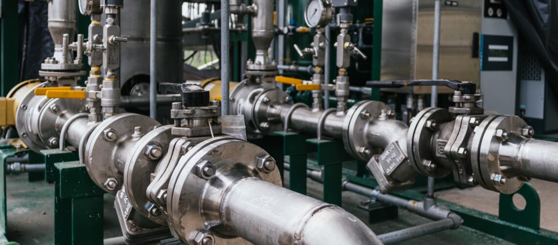
         This procedure applies to all piping materials, including pipes, fittings, flanges, valves, gaskets, bolts, and other components used in the construction of piping systems

      III. References

      •    ASME B31.3, Process Piping
      •    ASME Section II, Materials
      •    Project Piping Material Specification
      •    Approved Piping Drawings and Material Take-Offs (MTOs)
      •    Purchase Orders
      •    ASTM Standards (as applicable to specific materials)
      •    Company Quality Control Manual

      IV. Responsibilities

      •    Procurement Department: Responsible for ensuring that purchase orders accurately reflect the project’s material requirements
      •    Receiving Inspector: Responsible for performing the receiving inspection in accordance with this procedure
      •    Quality Control (QC) Engineer: Responsible for overseeing the receiving inspection process and resolving any non-conformance issues
      •    Material Controller: Responsible for maintaining material traceability and storage

      V. Procedure

      A. Pre-Receiving Activities

      • 1.  Review Documentation: Before material arrives, the Receiving Inspector shall review the Purchase Order, Material Requisition, Piping Material Specification, and approved drawings to understand the material
      • 2.  Prepare Inspection Area: Ensure a designated receiving area is available with adequate lighting, measuring tools, and access to relevant specifications
      • 3.  Obtain Approved Vendor List: Verify that the material supplier is an approved vendor per the project’s quality control requirements.

      B. Receiving Inspection Steps

      1.  Visual Inspection:

      •        Verify Packing List: Check the packing list against the purchase order to confirm the correct quantity and description of materials received
      •        Inspect for Damage: Carefully examine all materials for any signs of damage during shipping, such as dents, bends, corrosion, or broken packaging.
      • Document any damage on the receiving report and notify the supplier        
      • Check for Proper Marking: Verify that each item is clearly and legibly marked with the correct material grade, size, schedule, and heat number.
      • Markings should comply with applicable standards (e.g., ASME, ASTM)

      2.  Material Verification:

      •        Review Material Test Reports (MTRs): Obtain and review the MTRs (also known as Certified Material Test Reports or CMTRs) for each material lot
      •        Compare MTRs to Specifications: Verify that the chemical composition, mechanical properties (tensile strength, yield strength, elongation), and heat treatment listed on the MTRs meet the requirements of the applicable material specification (e.g., ASTM A106 Grade B, ASTM A105) and the project piping material specification
      •        Verify Traceability: Ensure that the heat number on the MTR matches the heat number marked on the material
      • This confirms traceability of the material back to its origin
      •        Positive Material Identification (PMI): For critical applications or materials susceptible to mix-ups (e.g., alloy steels), perform PMI using a portable spectrometer to verify the material’s chemical Document PMI results

      3.  Dimensional Verification:

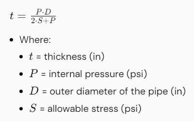
      •        Check Dimensions: Using calibrated measuring tools (e.g., calipers, tape measure), verify that the dimensions of the received materials (pipe diameter, wall thickness, flange dimensions, fitting dimensions) conform to the specified standards and the project drawings
      •        Verify Wall Thickness: Use ultrasonic thickness testing to verify the wall thickness of pipes and fittings, especially for corrosion-resistant alloys.

      4.  Specific Component Checks:

      •        Pipes: Check for straightness, ovality, and surface defects
      •        Fittings: Verify the angle, radius, and end preparation (e.g., bevel angle for welding
      •        Flanges: Check flange face finish, bolt hole alignment, and dimensions
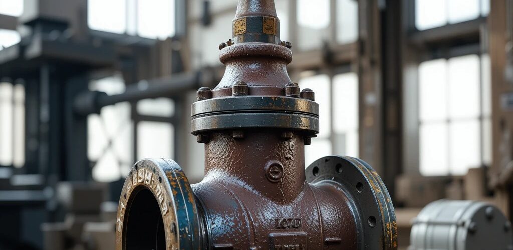
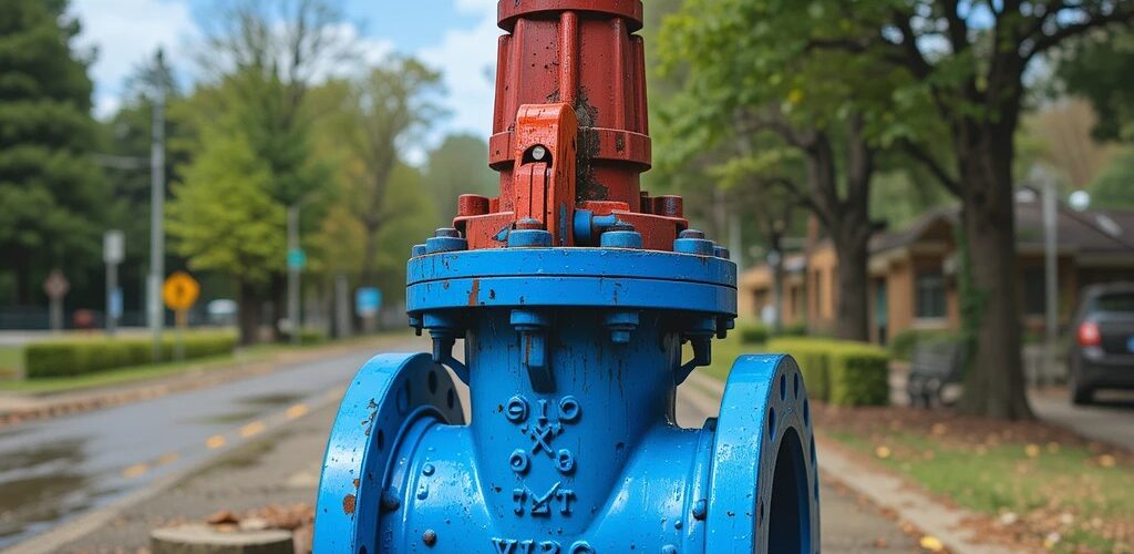
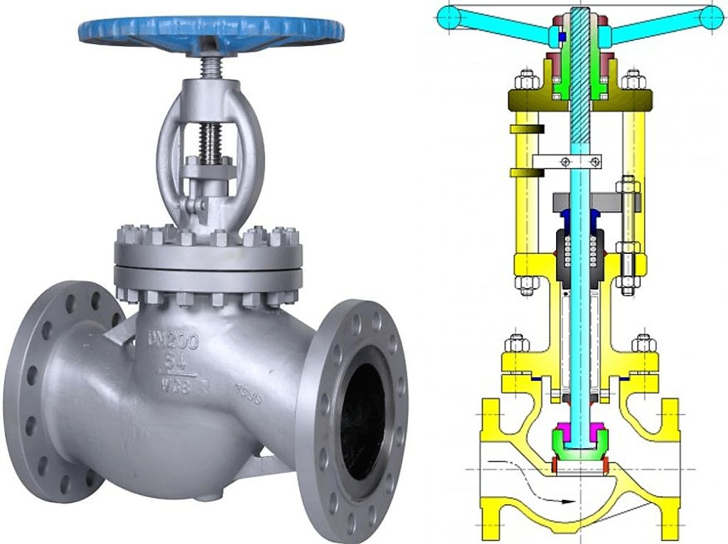
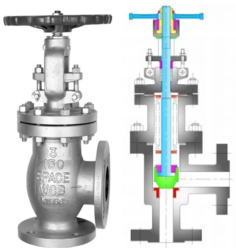
      •        Valves: Verify valve type, pressure rating, end connections, and operator type. Check for smooth valve operation
      •        Bolting: Verify bolt diameter, length, material grade, and thread
      •        Gaskets: Check gasket type, size, and material compatibility with the intended

      5.  Documentation:

      •        Complete Receiving Inspection Report: Document all inspection results on a receiving inspection report, including the purchase order number, material description, quantity inspected, inspection date, inspector’s name, and any discrepancies or non-conformances
      •        Attach MTRs: Attach copies of the MTRs to the receiving inspection
      •        Maintain Records: Maintain a file of all receiving inspection reports, MTRs, and related documentation for future

      C. Non-Conformance Handling

      • 1.  Identify Non-Conformances: Any material that does not meet the specified requirements shall be identified as non-conforming
      •  2.  Segregation: Segregate non-conforming materials from conforming materials to prevent accidental use
      • 3.  Notification: Notify the QC Engineer and Procurement Department of the non-conformance
      • 4.  Disposition: The QC Engineer will determine the appropriate disposition of the non-conforming material, which may include:
      •        Return to Supplier: Return the material to the supplier for replacement or credit
      •        Repair: Repair the material, if possible, and re-inspect to verify conformance
      •        Use-as-is: Accept the material “as-is” with a deviation, if it is determined that the non-conformance does not affect the safety or functionality of the piping system. This requires approval from the Engineering Department and the client, if
      • 5.  Documentation: Document the non-conformance and the resolution on a Non-Conformance Report (NCR)

      D. Material Storage and Handling

      • Proper Storage: Store materials in a clean, dry, and secure area to prevent damage or deterioration
      • Material Identification: Maintain material identification throughout storage and handling
      • Handling Procedures: Use proper lifting and handling equipment to prevent damage to materials
      • Inventory Control: Implement an inventory control system to track the location and status of all piping materials

      VI. Acceptance Criteria

      •    Materials are accepted if they meet all the requirements of this procedure, the applicable material specifications, and the project piping material
      •    All documentation is complete and accurate
      •    There are no unresolved non-conformances

      VII. Training

         All personnel involved in the receiving inspection process shall be trained on this procedure and the relevant material specifications

      VIII. Records

      •    Receiving Inspection Reports
      •    Material Test Reports (MTRs)
      •    Non-Conformance Reports (NCRs)
      •    Purchase Orders
      •    Material Requisitions
      •    Calibration Records for Measuring Equipment
      •    PMI Reports

      This comprehensive procedure ensures that all piping materials are thoroughly inspected upon arrival at the job site, minimizing the risk of using non-conforming materials and ensuring the integrity of the piping system

      Remember to adapt this procedure to your specific project requirements and company standards.


      Basic procedure for conducting piping pressure tests based on ASME B31.3

      I. Purpose

      • To verify the integrity and leak-tightness of the constructed piping system before it is put into service
      • To ensure compliance with ASME B31.3 code requirements

      II. Scope

      • This procedure applies to all new piping systems and modified piping systems within the specified facility or project
      • It covers hydrostatic and pneumatic testing methods

      III. References

      • ASME B31.3, Process Piping
      • Project Piping Specifications
      • Approved Piping Drawings and Isometrics

      IV. Responsibilities

      • Piping Engineer: Responsible for determining the test pressure, test medium, and any special testing requirements
      • Construction Supervisor: Responsible for ensuring that the piping system is properly prepared for testing, including adequate supports and restraints
      • Quality Control Inspector: Responsible for witnessing and documenting the pressure test
      • Test Personnel: Responsible for performing the pressure test in accordance with this procedure

      V. Prerequisites

      • All piping fabrication and installation must be complete and inspected
      • All welds must be visually inspected
      • Piping system should be supported per the design requirements
      • Temporary supports may be needed to accommodate the weight of the test fluid
      • All components, including valves, fittings, and specialty items, must be properly installed and tightened
      • The piping system must be clean and free from debris
      • All connections not subject to the pressure test must be disconnected or isolated using blinds or other suitable methods
      • Pressure gauges must be calibrated and certified
      • Safety relief devices must be installed or provisions made to prevent over pressurization
      • All personnel involved in the test must be trained and familiar with this procedure and potential hazards

      VI. Test Medium

      • Hydrostatic Test: Potable water is the preferred test medium. If water could damage the system or cannot be used due to freezing, a suitable non-toxic liquid with a flash point above 120°F (49°C) may be used
      • Pneumatic Test: Clean, dry compressed air or nitrogen is used

      VII. Test Pressure

      • Hydrostatic Test Pressure: Calculated per ASME B31.3, para. 345.4.2
        The test pressure shall be 1.5 times the design pressure multiplied by the ratio of the allowable stress at the test temperature to the allowable stress at the design

      Globe Valves

      Globe Valve Types based on Body Bonnet Connection


      Screwed bonnet: This is the simplest design available and it is used for inexpensive valves.
      Bolted-bonnet: This is the most popular design and used in a large number of globe valves. This requires a gasket to seal the joint between the body and bonnet.
      Welded-Bonnet: This is a popular design where disassembly is not required. They are lighter in weight than their bolted-bonnet counterparts.
      Pressure-Seal Bonnet: This type is used extensively for high-pressure high-temperature applications. The higher the body cavity pressure, the greater the force on the
      gasket in a pressure -seal valve.

      Application of Globe valve
      Globe Valves are used in the systems where flow control is required and leak tightness is also important.
      It used in high-point vents and low-point drains when leak tightness and safety are major concerns. Otherwise, you can use a gate valve for drain and vent.
      It can be used in Feed-water, chemical, air, lube oil and almost all services where pressure drop is not an issue
      This valve is also used as an automatic control valve, but in that case, the stem of the valve is a smooth stem rather than threaded and is opened and closed by lifting action of an actuator assembly.

      Advantages
      Better shut off as compared to gate valve
      Good for frequent operation as no fear of wear of seat and disk
      Easy to repair, as seat and disk can be accessed from the valve top
      Fast operation compares to gate valve due to shorter stroke length
      Usually operated by an automatic actuator

      Disadvantages
      High head loss from two or more right-angle turns of flowing fluid within the valve body.
      Obstructions and discontinuities in the flow path lead to a high head loss.
      In a large high-pressure line, pulsations and impacts can damage internal trim parts.
      A large valve require considerable power to open and create noise while in operation.
      It is heavier than other valves of the same pressure rating.
      Costlier compared to the gate valve


      Types of Globe Valve

      Depending on the type of body there are three types of globe valves;

      • Z types
      • Y types
      • Angle Types

      Z types Globe Valve

      The simplest design and most common type is a Z-body. The Z-shaped partition inside the globular body contains the seat. The horizontal seating arrangement of the
      seat allows the stem and disk to travel at a perpendicular to the pipe axis resulting in a very high-pressure loss.
      The valve seat is easily accessible through the bonnet which is attached to a large opening at the top of the valve body. Stem passes through the bonnet like a gate
      valve.
      This design simplifies manufacturing, installation, and repair. This type of valve is used where pressure drop is not a concern and throttling is required.

      Y types Globe Valve

      The Y-type design is a solution for the high-pressure drop problem in Z-type valves. In this type, seat and stem are angled at approximately 45° to the pipe axis. Y-body valves are used in high pressure and other critical services where pressure drop is concerned.

      Angle types Globe Valve

      Angle globe valve turns the flow direction by 90 degrees without using an elbow and one extra pipe weld. Disk open against the flow. This type of globe valve can be
      used in the fluctuating flow condition also, as they are capable of handling the slugging effect.


      Note#112

      CF8 vs CF8M, CF8M contains 2% to 3% molybdenum that CF8 does not have


      Note#111

      Stainless steels may be classified by their crystalline structure into four main types: austenitic, ferritic, martensitic and duplex


      Note#110

      Difference between 304 and 316 stainless steel?
      The simple answer is 304 contains 18% chromium and 8% nickel while 316 contains 16% chromium, 10% nickel and 2% molybdenum. The molybdenum is added to help resist corrosion to chlorides (like sea water and deicing salts)


      Note#109

      Stress Analysis

      • Permissible load variation is determined as the ratio of (Travel x Spring rate / Load ) based on max. operating condition.
      • Cold Load = Hot Load + Movement x Spring Rate (For pipe movement up)
      • Cold Load = Hot Load – Movement x Spring Rate (For pipe movement down)
      • the load variability shall be up to 25% throughout the total travel. However, for critical systems such as piping connected to pumps, compressors, reboilers, etc. lesser load variation is required to meet the allowable load requirements.
      • if the load variation exceeds the allowed value, in the same load range selects a spring with lower spring rate. Else, select higher size spring.

      Note#108

      Strainers

      • If the application requires that the system has to run continuously and cannot be shut down, then the only real choice is a duplex basket strainer.
      • If a vertical installation is planned, a Y-Strainer is the one that will work. Y-Strainers can be installed either vertically or horizontally. A basket strainer must be installed horizontally.


      Note#107

      For Cold Service Bolting torque to develop 70% Bolt Yield Stress at Nut Factor, K=0.16 (Nut Factor based on lubricant used)