Tells how much water the valve can pass when it is fully open with pressure drop 1 bar accross it
Unit is m3/hr
Kv= Cv * 0.865
Design-Engineering-Construction-Testing & Commissioning of piping

Tells how much water the valve can pass when it is fully open with pressure drop 1 bar accross it
Unit is m3/hr
Kv= Cv * 0.865
Tells how much water the valve can pass when it is fully open with pressure drop 1 psi accross it
The unit is gallon/minute
Thermal relief valve should be set to pressure less than design pressure and higher than operating pressure because its design is small in size, so it will not discharge high flow
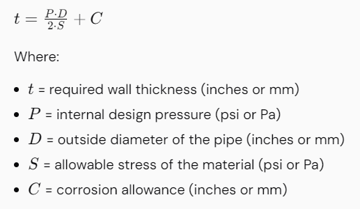
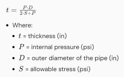
Calculating the wall thickness of a pipe is essential for ensuring the structural integrity and safety of piping systems, especially under internal pressure. The following steps outline how to calculate the pipe wall thickness based on ASME standards, particularly ASME B31.3 for process piping.
For an internally pressurized pipe, the minimum required thickness can be calculated using the following formula from ASME B31.3:
Note: For specified thickness definitions within ASME, you may also include a term for the minimum wall thickness. This can be specifically stated in different ASME sections.
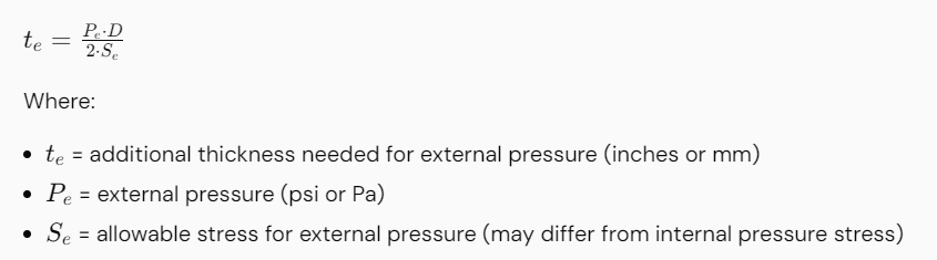
If the pipe is subject to external pressure, you must also consider the external pressure when calculating the wall thickness. Use the formula:
Combine thicknesses computed for internal and external pressures:
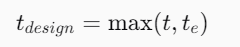
This equation helps in determining the final design thickness, accounting for both internal and external pressures.
Check if the calculated wall thickness meets or exceeds available standard pipe sizes and schedules (such as Schedule 40, 80). Pipe thicknesses defined by ASME pipe schedule can be found in ASME B36.10 and ASME B36.19.
Include any additional factors such as:
Adjust the thickness accordingly if required by safety factors or specific application standards.
Ensure the final design meets all relevant codes and standards (such as ASME B31.3, B31.1, etc.) and industry best practices. Perform peer reviews or checks per organizational procedures.
Calculating pipe wall thickness using ASME standards requires a comprehensive understanding of the operational conditions, material properties, and appropriate mathematical formulas. Consider the internal and external pressures, allowable stress, and corrosion allowances to ensure safety and compliance. This process is critical for the design, material selection, fabrication, and maintenance planning of piping systems. Always refer to the latest ASME codes and standards for the most accurate and safe design practices.
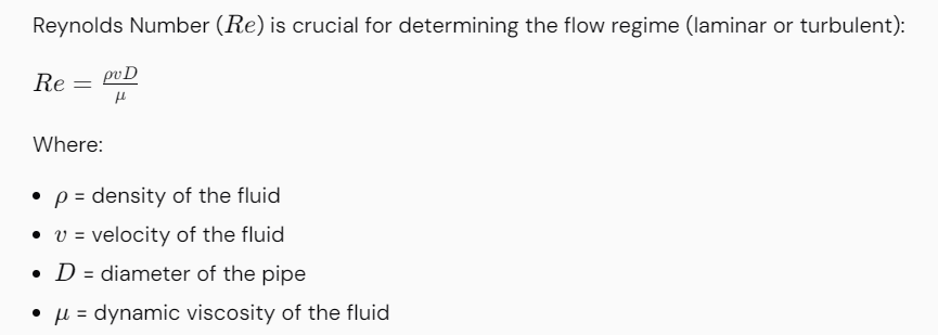
Calculating pressure drop in piping systems is a crucial aspect of engineering design. It helps in understanding the hydraulic performance of a pipeline and ensuring the system operates efficiently. The following steps outline the method to calculate pressure drop in a piping system based on ASME standards.


Using the flow rate, calculate the fluid velocity in the pipe:
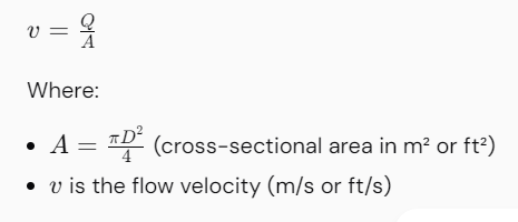
Note:
Where:

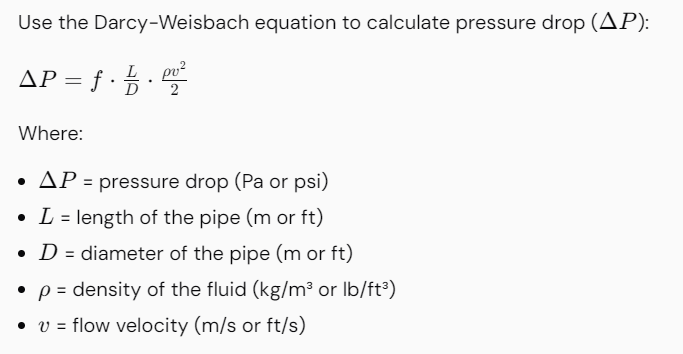
Consider fittings, bends, valves, and other components in the piping system that contribute to pressure drop:
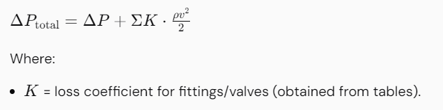
Add up the pressure drop from the straight pipe and all additional components to find the total pressure drop across the entire system.
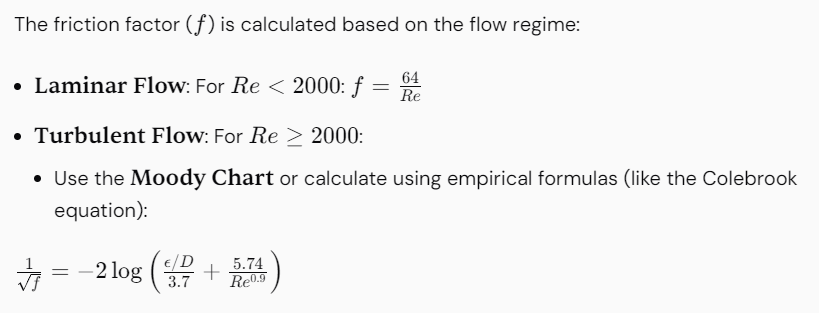
The calculation of pressure drop in piping based on ASME standards involves understanding fluid properties, determining the flow regime, calculating friction factors, and applying the Darcy-Weisbach equation. Additional losses due to fittings and other components should also be considered. Always refer to relevant reference materials and standards for specific guidelines. This method will provide the necessary calculations to ensure efficient system design and operability.
Hot tapping is a technique used to create a connection to an existing pressurized pipe system without having to drain the system. Calculating the requirements for a hot tap involves several steps, including determining the size of the hot tap, assessing the pipe’s operating conditions, ensuring safety, and calculating any necessary factors like pressure and flow. Below is a systematic approach to hot tap calculations:
Using the ASME Boiler and Pressure Vessel Code, the wall thickness can be calculated based on the pipe diameter, material, and pressure parameters. Use formulas such as:
If there will be a flow through the new branch connection, perform calculations to ensure the desired flow rate is achieved. Use equations:

Hot tap calculations involve understanding the specifications of the pipe, calculating the required wall thickness, selecting the appropriate fittings, and ensuring safety considerations are met. The calculations help guarantee that the hot tap process is safe and effective, maintaining the integrity of the existing pipeline while allowing for new connections. Always refer to relevant codes and engineering practices for more specific guidelines tailored to your operation.
Conducting a complex piping design analysis involves multiple steps that encompass planning, modeling, analysis, and optimization. Below is a comprehensive guide on how to perform such an analysis:
By following these steps, you can achieve an accurate and thorough complex piping design analysis, ensuring that the system is safe, efficient, and compliant with industry standards.
A simple piping design analysis involves several key steps to ensure the safety and efficiency of the system . Here’s a breakdown of how to perform one:
1. Define the System :
2. Determine Pipe Size and Schedule:
3. Calculate Pressure Drop:
4. Layout and Routing :
5. Model the System:
6. Support Design:
7. Stress Analysis :
8. Flexibility Analysis:
9. Evaluate the Results:
10. Optimize the Design:
* If the analysis reveals areas of concern, adjustments should be made to the design . Common solutions include:
* Adding or repositioning supports
* Incorporating expansion loops or joints
* Modifying the layout to reduce stresses
* Changing the material or wall thickness of the pipe
11. Verify Compliance:
* Ensure that the final design meets all relevant codes and standards .
Weight of water in pipes filled with water can be calculated as
ww = 0.3405 di 2 (3)
where
ww = weight of steel pipe filled with water (Pounds per Foot Pipe)
di = inside diameter (inches)
Weight of Empty Steel Pipes
Weight of empty steel pipes can be calculated in imperial units as
wp = 10.6802 t (do – t) (2)
where
wp =weight of steel pipe (Pounds per Foot Pipe)
t = pipe wall thickness (Inches)
do = outside diameter (inches)
Or. alternatively in metric units
wp = 0.02464 t (do – t) (2b)
where
wp =weight of steel pipe (kg/m)
t = pipe wall thickness (mm)
do = outside diameter (mm)
Cross Sectional Area
Cross-sectional Area of a Steel Pipe can be calculated as
A = 0.785 di 2 (1)
where
A = cross-sectional area of pipe (Square Inches)
di = inside diameter (inches)