GRE piping have a good resistance to chlorine but GRP piping not resist it
Design-Engineering-Construction-Testing & Commissioning of piping

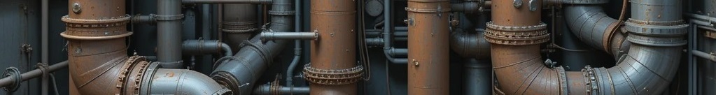
GRE pipe stands for Glass Reinforced Epoxy pipe, which is a composite material made from high-strength fiberglass and epoxy resin. It is used in a variety of applications, especially in corrosive or high-pressure environments where its high strength, excellent chemical resistance, and long lifespan are advantageous over traditional materials like steel. Common uses include industrial systems, offshore platforms, and various shipbuilding applications
GRP pipes are high-performance pipes made from Glass Reinforced Polymer (also called Glass Reinforced Plastic), which consists of glass fibers, polyester resins, and fillers. They are known for being strong, durable, lightweight, and resistant to corrosion and chemicals, making them ideal for applications like water and sewer lines, drainage, and industrial fluid transport. Their smooth internal surface promotes efficient flow, and their longevity and low maintenance result in a favorable lifecycle cost
Thermal relief valve should be set to pressure less than design pressure and higher than operating pressure because its design is small in size, so it will not discharge high flow
Sized surge tank (open or bladder type) is objectively safer and more reliable than a surge anticipator valve, because it has no moving parts and absorbs the surge instantly and forever.
In practice, however, surge anticipator valves are installed 20× more often because they are cheaper, smaller, and work well enough (75–90% reduction) for most buildings.
The surge anticipator valve (also called surge anticipation valve or pressure-anticipator relief valve) is a special automatic valve installed on the discharge side of fire pumps, booster pumps, or any pump that can create dangerous water hammer when it starts or stops suddenly.
Its only job is to protect the piping system from extreme pressure spikes caused by hydraulic transients (water hammer)
Common Causes of Water Hammer
For fixed orifice double regulating valves, a minimum of 5 pipe diameters of straight pipe (without intrusion) should be installed upstream of the orifice plate, and a minimum of 2 pipe diameters of straight pipe are required downstream of the valve
Minimum corrosion allowance for stainless steels is 0.8 mm
Minimum corrosion allowance of 1.5 mm shall be provided for carbon steel material
Stainless steels may be classified by their crystalline structure into four main types: austenitic, ferritic, martensitic and duplex
Difference between 304 and 316 stainless steel?
The simple answer is 304 contains 18% chromium and 8% nickel while 316 contains 16% chromium, 10% nickel and 2% molybdenum. The molybdenum is added to help resist corrosion to chlorides (like sea water and deicing salts)
Stress Analysis
Strainers
For Cold Service Bolting torque to develop 70% Bolt Yield Stress at Nut Factor, K=0.16 (Nut Factor based on lubricant used)
Bolting torque to develop 50% Bolt Yield Stress at Nut Factor, K=0.16 (Nut Factor based on lubricant used)
if the vessel is protected by multiple relief devices, then one relief device must be set no higher than the MAWP but the others can be set as high as 105% of the MAWP.