High pressure may result from the failure of a control valve, a reaction that is out of control, thermal expansion of a liquid, or even an external fire.
Design-Engineering-Construction-Testing & Commissioning of piping

High pressure may result from the failure of a control valve, a reaction that is out of control, thermal expansion of a liquid, or even an external fire.
by increase the flange class inner diameter and diameter of the raised face at all the same; but outside diameter, bolt circle and diameter of bolt holes become larger in each higher pressure class.
| ASTM Group 2-1.1 Materials | ASTM Group 2-2.3 Materials | |||||||
| Nominal | Forgings | Castings | Plates | Nominal | Forgings | Castings | Plates | |
| Designation | Designation | |||||||
| C-Si | A105(1) | A216 | A515 | 16Cr 12Ni 2Mo | A182 | … | A240 | |
| Gr.WCB(1) | Gr.70(1) | Gr.F316L | Gr.316L | |||||
| C Mn Si | A350 | … | A516 | 18Cr 13Ni 3Mo | A182 | … | … | |
| Gr.LF2(1) | Gr.70(1),(2) | Gr.F317L | ||||||
| C Mn Si V | A350 | … | A537 | 18Cr 8Ni | A182 | … | A240 | |
| Gr.LF6 Cl 1(3) | Cl.1(4) | Gr.F304L(1) | Gr.304L(1) | |||||
| 3.1/2Ni | A350 | … | … | |||||
| Gr.LF3 | ||||||||
| Notes: | Note: | |||||||
| (1) Do not use over 425°C. | ||||||||
| (1) Upon prolonged exposure to temperatures above 425°C, the carbide phase of steel may be converted to graphite. Permissible but not recommended for prolonged use above 425°C. | ||||||||
| (2) Do not use over 455°C. | ||||||||
| (3) Do not use over 260°C. | ||||||||
| (4) Do not use over 370°C. | ||||||||
| Pressure-Temperature Ratings for ASTM Group 2-1.1 Materials | |||||||
| Working pressure by Classes, BAR | |||||||
| Temp °C | 150 | 300 | 400 | 600 | 900 | 1500 | 2500 |
| -29 to 38 | 19.6 | 51.1 | 68.1 | 102.1 | 153.2 | 255.3 | 425.5 |
| 50 | 19.2 | 50.1 | 66.8 | 100.2 | 150.4 | 250.6 | 417.7 |
| 100 | 17.7 | 46.6 | 62.1 | 93.2 | 139.8 | 233 | 388.3 |
| 150 | 15.8 | 45.1 | 60.1 | 90.2 | 135.2 | 225.4 | 375.6 |
| 200 | 13.8 | 43.8 | 58.4 | 87.6 | 131.4 | 219 | 365 |
| 250 | 12.1 | 41.9 | 55.9 | 83.9 | 125.8 | 209.7 | 349.5 |
| 300 | 10.2 | 39.8 | 53.1 | 79.6 | 119.5 | 199.1 | 331.8 |
| 325 | 9.3 | 38.7 | 51.6 | 77.4 | 116.1 | 193.6 | 322.6 |
| 350 | 8.4 | 37.6 | 50.1 | 75.1 | 112.7 | 187.8 | 313 |
| 375 | 7.4 | 36.4 | 48.5 | 72.7 | 109.1 | 181.8 | 303.1 |
| 400 | 6.5 | 34.7 | 46.3 | 69.4 | 104.2 | 173.6 | 289.3 |
| 425 | 5.5 | 28.8 | 38.4 | 57.5 | 86.3 | 143.8 | 239.7 |
| 450 | 4.6 | 23 | 30.7 | 46 | 69 | 115 | 191.7 |
| 475 | 3.7 | 17.4 | 23.2 | 34.9 | 52.3 | 87.2 | 145.3 |
| 500 | 2.8 | 11.8 | 15.7 | 23.5 | 35.3 | 58.8 | 97.9 |
| 538 | 1.4 | 5.9 | 7.9 | 11.8 | 17.7 | 29.5 | 49.2 |
| Pressure-Temperature Ratings for ASTM Group 2-2.3 Materials | |||||||
| Working pressure by Classes, BAR | |||||||
| Temp °C | 150 | 300 | 400 | 600 | 900 | 1500 | 2500 |
| -29 to 38 | 15.9 | 41.4 | 55.2 | 82.7 | 124.1 | 206.8 | 344.7 |
| 50 | 15.3 | 40 | 53.4 | 80 | 120.1 | 200.1 | 333.5 |
| 100 | 13.3 | 34.8 | 46.4 | 69.6 | 104.4 | 173.9 | 289.9 |
| 150 | 12 | 31.4 | 41.9 | 62.8 | 94.2 | 157 | 261.6 |
| 200 | 11.2 | 29.2 | 38.9 | 58.3 | 87.5 | 145.8 | 243 |
| 250 | 10.5 | 27.5 | 36.6 | 54.9 | 82.4 | 137.3 | 228.9 |
| 300 | 10 | 26.1 | 34.8 | 52.1 | 78.2 | 130.3 | 217.2 |
| 325 | 9.3 | 25.5 | 34 | 51 | 76.4 | 127.4 | 212.3 |
| 350 | 8.4 | 25.1 | 33.4 | 50.1 | 75.2 | 125.4 | 208.9 |
| 375 | 7.4 | 24.8 | 33 | 49.5 | 74.3 | 123.8 | 206.3 |
| 400 | 6.5 | 24.3 | 32.4 | 48.6 | 72.9 | 121.5 | 202.5 |
| 425 | 5.5 | 23.9 | 31.8 | 47.7 | 71.6 | 119.3 | 198.8 |
| 450 | 4.6 | 23.4 | 31.2 | 46.8 | 70.2 | 117.1 | 195.1 |
Flanges can withstand different pressures at different temperatures. As temperature increases, the pressure rating of the flange decreases
Slug Flow is typical two phase flow where a wave is picked up periodically by the rapidly moving gas to form a frothy slug, which passes along the pipe at a greater velocity than the average liquid velocity.
Data required for flexibility calculations
1. Code of Practice
2. Basic Material of Construction of Pipe
3. Ambient / Installation temperature
4. Number of Thermal Cases
5. Flexibility Temperature (See Note)
6. Design Pressure
7. Outside diameter of Pipe
8. Type of construction of pipe
9. Nominal Thickness of Pipe
10. Manufacturing tolerance
11. Corrosion allowance
12. Pipe Weight
13. Insulation Weight
14. Specific Gravity of Contents
15. Young’s Modulus at Ambient/Installation Temperature
16. Young’s Modulus at Flexibility Temperature
17. Thermal Expansion at Flexibility Temperature
18. Allowable stress at Ambient/ Installation temperature
19. Allowable stress at flexibility temperature
20. Bend radius and type of bend
21. Branch connection type
22. Weight of attachments – Valves and Specialties
23. Terminal movements with directions
Types of fluid service according to B31.3
(a) Category D Fluid Service: a fluid service in which all the following apply:
(1) the fluid handled is nonflammable, nontoxic, and not damaging to human tissues as defined in para.300.2;
(2) the design gage pressure does not exceed 1035 kPA (150 psi);
(3) the design temperature is from −29°C (−20°F) through 186°C (366°F).
(b) Category M Fluid Service: a fluid service in which the potential for personnel exposure is judged to be significant and in which a single exposure to a
very small quantity of a toxic fluid, caused by leakage, can produce serious irreversible harm to persons on breathing or bodily contact, even when prompt restorative
measures are taken
(c) High Pressure Fluid Service: a fluid service for which the owner specifies the use of Chapter IX for piping design and construction; see also para. K300
(d) Normal Fluid Service: a fluid service pertaining to most piping covered by this Code, i.e., not subject to the rules for Category D, Category M, or High
Pressure Fluid Service
Pressure gauge normally indicates the difference between the measured pressure (absolute pressure) and atmospheric pressure.
On the long term negative effects of rusting on steel valves will reduce the structural integrity of the valve, since rust has different physical characteristics than steel
Zinc, aluminum and magnesium are more electronegative than steel they are increasingly able to supply electrons to the more electropositive steel when in electrical contact in water,
Cathodic protection may be achieved in either of two ways. By the use of an impressed current from an electrical source, or by the use of sacrificial anodes (galvanic action).
You can protect piping which in contact with the ground or routinely contains fuel by one of the following methods
made of a non-corrodible material (such as fiberglass or flexible plastic)
made of steel and coated and cathodically protected
made of steel and cathodically protected
isolated from contacting the earth by being inside some form of secondary containment that is made of a non-corrodible material
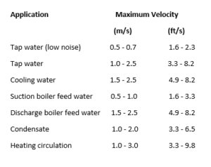
The fluid flow velocities in water systems should not exceed certain limits to avoid noise and damaging wear and tear of pipes and fittings. The table below can be used as guidance to maximum velocities:
Weight of pipe filled with water
Categories: Calculations

Categories: Articles


Categories: Articles
Categories: Articles